
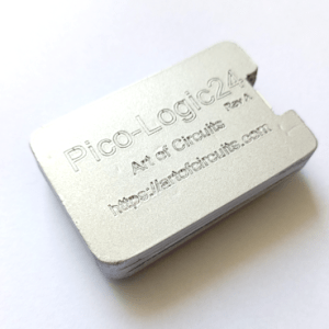
Pico-Logic24 A 24 Channel Analog and Digital Logic Analyzer – 10M Max Sample Rate
BOA BALL PEN
Product Code: TPC551905
A high gloss twist action ball pen, made in Germany using climate-neutral production and 100% green electricity. 20% of the plastic used to produce this product is made from recycled ABS plastic! This promotional pen is made to order and you can customise the individual parts of the pen. You can pick between a wide range of 14 different standard colours and from 3000pcs you can even pantone match the parts! This twist action ball pen is sure to stand out, not only with your colour combinations, but also the sleek and precise design will catch the attention of anyone. Supplied with a quality Silktech refill, made of recycled PP material, that is guaranteed to have a write out length of 3000m and can be supplied in blue or black ink. A combination of precise design and engineering oozes quality and ensures a writing experience like no other. Get in touch today and order now!
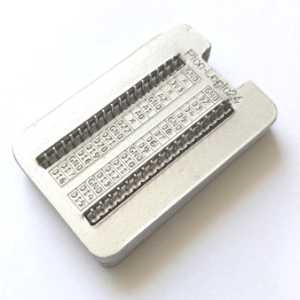
Description Product Description The PicoLogic24 transforms is ab affordable USB logic analyzer and basic oscilloscope. the PicoLogic offers high-speed digital signal capture previously only seen in much more expensive dedicated hardware. Fully compatible with PulseView graphical interface, the Pico-Logic24 provides essential tools for debugging embedded systems, analyzing communication protocols like I2C, SPI, UART, and more. With its extensive library of protocol decoders and basic math functions, the Pico-Logic24 is your go-to solution for understanding digital and basic analog signals. Whether you’re a hobbyist, student, or professional engineer, the Pico-Logic24 offers exceptional value for money in your test and measurement toolkit. Technical Specifications Digital Channels: Up to 21 channels (GPIO 2-22 usable for digital capture) Digital Sampling Rate (Max): 10MSPS (for first 4 digital channels D2, D3,D4, D5) Analog Channels: 3 channels (ADC0, ADC1, ADC2, typically mapped to GPIO 26-28) Analog Sampling Rate (Max): Up to 500 kSamples/second (kS/s) for Single Analog channel, but max analog bandwidth of Analog IO is 150KHz. Up to 2.0 MS/s (achievable via ADC clock overclocking, with minor accuracy trade-offs) Analog Resolution: 12-bit ADC, with an Effective Number of Bits (ENOB) of ~7-8 bits in practice. Logic Levels: 3.3V tolerant inputs only. (See Limitations below for 5V signals). Memory Depth: Limited by upto 200KB Memory for burst captures. For continuous streaming, memory depth is dependent on your host PC’s RAM and USB bandwidth. Interface to Host PC: USB 1.1 Full-Speed (12 Mbps) via micro-USB/USB Type C port. Supported Protocol Decoders PulseView, powered by libsigrokdecode, offers a vast and ever-growing library of protocol decoders to automatically interpret your captured digital signals into human-readable data. This greatly simplifies debugging complex communications. Some of the many supported protocols include: Standard Serial: UART (Universal Asynchronous Receiver/Transmitter) I2C (Inter-Integrated Circuit) SPI (Serial Peripheral Interface) 1-Wire RS-232, RS-485 Automotive/Industrial: CAN (Controller Area Network) LIN (Local Interconnect Network) DALI (Digital Addressable Lighting Interface) DMX512 (Digital MultipleX 512) Memory & Storage: SD Card (SPI mode) EEPROM (24xx I2C, 93xx Microwire) Flash (e.g., MX25Lxx05D) Display & Video: HDMI-CEC (Consumer Electronics Control) EDID (Extended Display Identification Data) LCD (e.g., Amulet ASCII) Debug & Trace: JTAG (Joint Test Action Group – IEEE 1149.1) cJTAG (Compact JTAG – IEEE 1149.7) SWD (Serial Wire Debug) AVR ISP, AVR PDI ARM ETMv3, ARM ITM, ARM TPIU Wireless/RF: CC1101 (TI low-power RF transceiver) EM4100/EM4305 (RFID) Sensors: AM230x/DHTxx (Humidity/Temperature) ADXL345 (Accelerometer) DS18B20 (1-Wire Digital Thermometer) ADNS-5020 (Optical Mouse Sensor) Other/Specialized: USB (low/full speed) Ethernet (basic frame decoding) AC ’97 (Audio Codec) PS/2 (Keyboard/Mouse) MIDI Digital Calipers DCF77 (Time Protocol) Parallel Bus (configurable for various synchronous parallel buses) Many more, with new decoders continuously being added by the open-source community. Many decoders can be stacked (e.g., decoding SPI, then feeding that output into an AVR ISP decoder) for multi-layered analysis. Limitations Please be aware of the following inherent limitations of the PicoLogic24 USB Bandwidth: The Pico’s USB 1.1 (Full-Speed) interface can be a bottleneck for very high-speed, long-duration continuous captures, potentially leading to sample drops if the data rate exceeds the USB transfer capability. Analog Resolution: While capable of basic analog capture, the 7-8 bit effective resolution is suitable for general signal inspection but not for high-precision analog measurements. Logic Level Incompatibility: The RP2040 GPIOs are 3.3V logic only. Applying 5V or higher logic levels directly to the inputs WILL DAMAGE THE LOGIC ANALYZER. Always use appropriate logic level shifters when connecting to 5V systems. Memory Depth for Burst Captures: The 264KB on-chip SRAM limits the maximum number of samples that can be buffered during a burst capture before data needs to be streamed to the PC. Triggering: While some hardware triggering is possible in certain firmware versions, the primary triggering mechanism often relies on the host PC’s software, which can introduce minor latency. Max Sampling Rate Limitations: 1-4 Channels – 10MHz – without Analog Channels enabled 1-4 Channels – 10MHz(for Digital)/166KHz (for Analog) – with all 3 Analog Channels enabled 5-21 Channels – 3 MHz – without Analog Channels enabled Mechanical Specifications Form Factor: Based on the standard Raspberry Pi Pico board. Dimensions: 40 x 60 x 10 mm (without Header Height) 40 x 60 x 15 mm (with Header Height) Connectors: 1x Micro USB port for power and data communication. 2x 20-pin dual-row headers (0.1″ pitch) providing access to GPIOs. Documents and Downloads Logic Analyzer Software (Download link Supplied in email or through whatsapp) Package Includes 1x PicoLogic24 An 24 Channel Logic Analyzer in a Laser-cut PVC Case – QC OK by Art of Circuits 40x Female to Female 20cm Dupont cables
Product Size
146 x 15 mm
Additional Information
Price includes a one colour print to one position.
Lead Times
4 weeks from approval of artwork
Colours
Cyan,Light Blue,Mid Blue,Dark Blue,Dark Pink,Black,Dark Red,Dark Orange,Mid Orange,Yellow,White,Dark Grey,Cool Grey,Dark Green,Mid Green,Light Green
Carton Quantity
500
Carton Dimension
36 x 36 x 26 cm
No Stock Information is currently available, please contact sales for more information.
Pad/Screen Artwork
Pad/Screen Print Area
40 x 20 mm (barrel) 35 x 6 mm (clip)
No of Spot Colours
4
Notes
Price includes a one colour print to one position.
Same Day Service
100 - 1 Colour
Same 1 Day Service
250 - 1 Colour
Same 2 Day Service
500 - 1 Colour